A paper bursting strength tester records the peak hydraulic pressure at which a clamped sheet ruptures against a rubber diaphragm. When that number drifts while the instrument still looks healthy, the cause is almost always one of five things: pump rate, diaphragm condition, clamping pressure, trapped air, or pressure-sensor calibration. Work through them in that order.
Bursting strength is one of the few paper tests that a buyer, a converter and a mill laboratory can all argue about with the same vocabulary. It appears in purchase specifications, in incoming-inspection sheets, in linerboard grade descriptions and in carton performance claims. It is also one of the easiest tests to run badly, because the instrument hides most of its own faults. A tester with a stiff diaphragm, a partly blocked hydraulic line or a clamp that no longer seats flat will still close, still pressurise, still burst the sheet and still print a number. The number is simply wrong, and nothing on the display says so.
This guide is written for the person who owns that number: the laboratory technician who has to explain a 12 % drop between two shipments, the quality engineer writing a control plan, and the procurement manager trying to decide whether a specification of "not less than 700 kPa" is meaningful for the grade being bought. It covers what the instrument actually measures, how the main standards differ, how to read and report the result properly, the seven error sources that move a reading, how to separate verification from calibration, and what a realistic maintenance schedule looks like.

The specimen is clamped between two annular plates. Below the sheet sits a rubber diaphragm that seals a chamber filled with hydraulic fluid — usually glycerol, sometimes a glycol mixture or a low-viscosity silicone oil. A motor-driven piston pushes fluid into the chamber at a controlled rate, the diaphragm bulges upward, and the sheet is stretched until it ruptures. The pressure at the moment of rupture is the bursting strength, reported in kilopascals or pounds per square inch.
Three consequences follow from that geometry, and each one matters more than most operating manuals admit.
The pressure gauge does not read the pressure that the sheet alone resisted. It reads the pressure required to push a diaphragm plus a sheet until the sheet fails. Part of every reading is the diaphragm's own resistance to bulging, which is why the standards specify that resistance in mechanical terms rather than leaving it to the supplier. A conforming diaphragm resists roughly 170–220 kPa at a 10 mm bulge and 250–350 kPa at an 18 mm bulge, sits at a defined rest position below the clamp face, and is made from rubber of a defined hardness. A new diaphragm and a two-year-old diaphragm of the same nominal size are not the same measuring instrument.
This is also why the failure direction of a worn diaphragm is not predictable from the outside. A diaphragm that has stiffened adds more resistance than it should and pushes readings up. One that has softened, stretched or developed a permanent dome adds less and pulls readings down. A small nick near the clamp edge usually produces scatter rather than bias, because the rupture point moves around the annulus from specimen to specimen. In all three cases the instrument still functions, which is exactly the problem.
A tensile test pulls in one direction. A burst test strains the sheet equally in every direction in the plane at once, and the failure is therefore controlled by whichever direction runs out of extensibility first. In machine-made paper this is usually the cross direction: the sheet is stronger in tension along the machine direction but less able to stretch, so it reaches its limit earlier under equal biaxial strain. The classic rupture pattern — a rough H-shaped tear with the crossbar running across the machine direction — is the visible signature of that sequence.
The practical implication is that burst strength correlates well with tensile strength across a family of similar furnishes, but not between furnishes with very different stretch. Two sheets of equal tensile strength will not have equal burst strength if one is substantially more extensible. This is the single most common source of confusion when a mill changes refining strategy, adds a strength additive, or switches to a furnish with more recycled fibre: tensile holds, burst moves, and nobody can explain why. The explanation is usually stretch.
Bursting strength responds to fibre length, fibre bonding, formation, moisture content and sheet density, all at once. That makes it an excellent production control parameter, because it moves when the process moves. It also makes it a poor absolute descriptor of a material, because two sheets with the same burst value can reach that value through quite different combinations of bond strength and stretch. Treat the number as a fingerprint of a process, not as a fundamental property, and most of the arguments about "the same paper" testing differently disappear.
Bursting strength is covered by several standards that share one physical principle but differ in orifice size, pumping rate, clamping rules, replicate counts and reporting. Using the wrong one is not a small administrative error: the numbers are not interchangeable, and a specification written against one method cannot be verified against another without a formal correlation study.
| Material | Typical method | Hydraulic rate | Typical reading | Report as |
|---|---|---|---|---|
| Paper, tissue, sack kraft up to about 0.6 mm | ISO 2758; TAPPI T 403; ASTM D774 | About 95 mL/min | Hundreds of kPa | kPa, plus burst index |
| Paperboard, linerboard, solid board | ISO 2759 | 170 mL/min | Hundreds to low thousands of kPa | kPa per surface, plus burst index |
| Corrugated fibreboard | TAPPI T 810; ISO 2759 practice | 170 mL/min | 500–1,200 kPa typical | kPa, with a note if flutes collapsed |
| Towel, tissue, nonwoven | Ball-burst practice (steel ball instead of diaphragm) | Per equipment | Depends on grade | Force, not pressure |
The distinction between the paper and board methods is not cosmetic. The board method uses a higher pumping rate so that thick, stiff material still ruptures within a sensible time, and it allows separate results for the two surfaces, because the wire side and the felt side of a board do not always behave identically. If a specification quotes a single burst value without naming the standard, the first question to ask is which material class it belongs to.
For corrugated board there is an additional reporting obligation that is frequently skipped: whether the flutes collapsed during the test. Flute collapse changes the mechanics of the rupture and is a legitimate observation about the board's construction, not a test failure. A laboratory that reports only the mean value is discarding evidence that the converter would find useful.
Raw bursting strength rises with grammage. A 200 g/m² board will out-burst a 120 g/m² board made from a better furnish, and comparing the two numbers directly tells you nothing about fibre quality. Burst index removes that dependency by dividing bursting strength by grammage, giving a value in kPa·m²/g. Two sheets of different weights can then be compared on the basis of how efficiently their fibre network converts mass into pressure resistance.
Grammage must be determined by the standard weighing method on the same conditioned sample, not estimated from the nominal grade. A 2 % error in grammage becomes a 2 % error in burst index, and nominal-versus-actual grammage differences of 3–5 % are routine in commercial board.
Clamping has to be firm enough to stop the specimen slipping and gentle enough not to damage it. The board method gives a graduated guide that increases with the strength of the material being tested, and requires the operator to use the lowest pressure within the permitted window that eliminates slip.
| Bursting strength of the sample | Indicative clamping pressure |
|---|---|
| Up to 1,500 kPa | About 400 kPa |
| 1,500–2,000 kPa | About 600 kPa |
| 2,000–2,500 kPa | About 800 kPa |
| Above 2,500 kPa | About 1,000 kPa |
Pneumatic clamping makes this reproducible, which is why it is worth the extra cost in any laboratory running more than a handful of tests a day. A hand wheel gives no feedback about how much pressure has actually been applied, and two operators will produce two different clamping loads from the same instruction to "tighten gently".
Repeatability is dominated by material variability, not by the instrument. Published interlaboratory data for board puts the coefficient of variation of individual results within a laboratory at roughly 4–8.5 %, with 95 % confidence limits on the mean of about ±2–4 %. Between laboratories the coefficient of variation on the mean rises to roughly 6–10 %. The practical conclusion is stark: a difference of less than about 5 % between two means measured on the same instrument, or less than about 10 % between instruments in different laboratories, is not evidence of a real difference in the material.
That number should be printed on the wall of every laboratory that issues pass or fail certificates against a customer limit. A substantial share of "failed" shipments are statistical noise, and a substantial share of "passed" shipments are noise in the other direction.
The board method asks for at least twenty valid bursts when a single result is required, or ten per surface when both faces are reported. Invalid tests must be discarded and replaced rather than averaged in:

The standards list the main sources of error in remarkably few words, and every one of them is a maintenance issue rather than an operator skill issue. What follows is the same list expanded into something a technician can act on, ordered by how often it is the actual culprit in a laboratory that has ruled out the obvious.
The hydraulic system must deliver fluid at a constant rate: roughly 95 mL/min for paper methods and 170 mL/min for board methods, each with a defined tolerance. Rate matters because the test is not instantaneous. A sheet that is pressurised slowly has time to creep and redistribute stress; a sheet that is pressurised quickly behaves more stiffly and bursts at a higher indicated pressure. Faster pumping therefore raises readings systematically, and slower pumping lowers them.
Pump rate drifts for boring reasons. Fluid viscosity changes as glycerol absorbs atmospheric moisture. A partially blocked line or a filter nearing the end of its life reduces flow. A pump that has been in service for years loses volumetric efficiency. None of these produces a dramatic failure; all of them produce a slow, plausible-looking trend that gets attributed to the paper.
The check is a timed volume measurement at the return line, compared with the standard's figure. It takes ten minutes and should be on the monthly schedule.
This is the highest-frequency cause of drift in most laboratories, and the least visible. The diaphragm is a consumable that lives in a hostile environment: it flexes thousands of times, is exposed to hydraulic fluid on one side and abrasive paper on the other, and slowly takes a set in the bulged position.
Three things need checking, and they are independent of one another:
Replacement intervals quoted by suppliers range from a few thousand tests to a fixed calendar period, whichever comes first. The honest rule is that the interval should be set from your own data: record the test count at each diaphragm change and the foil verification result immediately before it, and you will discover your own replacement point within two or three cycles.
Insufficient clamping lets the sheet slip inward as the diaphragm rises. The sheet draws material from outside the test area, thins locally and then fails at an artificially high pressure — or, more recognisably, wrinkles just outside the rupture and reads high. Uneven clamping does the same thing asymmetrically. The standards are explicit that inadequate or uneven clamping generally leads to an apparent increase in bursting strength.
Excessive clamping is the mirror image, and it is well documented in corrugated converting practice: over-clamping crushes the flute structure around the test area, pre-damages the board and produces a low value. The symptom is a burst that fails along a suspiciously straight line, or a board that looks compressed under the clamp ring after the test.
Both faults are visible on the specimen if anyone looks. A post-test inspection routine — clamp ring impression, wrinkle pattern, rupture shape, whether the failure is central or edge-initiating — catches most clamping problems before they become a trend in the data.
Hydraulic fluid is effectively incompressible; air is not. A bubble anywhere in the chamber or line absorbs volume before it transmits pressure, so the indicated peak arrives late and low, and successive readings scatter because the bubble moves. The standards note that air in the system generally leads to an apparent decrease in bursting strength.
Air enters through a loose fitting, a low fluid level, a fluid change done too quickly, or a diaphragm change where the chamber was not properly bled. The symptom pattern is distinctive: readings that are low and unstable rather than low and consistent, often with a visible hesitation on the pressure display during the ramp. Bleeding the circuit — loosening the reservoir fitting, gently flexing the diaphragm until no more bubbles appear at the reservoir, then resealing — resolves it in minutes.
Fluid level and fluid condition belong on the daily check. Glycerol that has absorbed water and picked up paper dust changes viscosity, which drags the pump rate with it, which brings you back to error source one.
The measuring system must be accurate to within about 10 kPa or 3 % of the reading, whichever is greater, and must respond fast enough that the displayed peak is within 3 % of the true peak. Those two requirements fail separately. A sensor can be accurate in steady state and still be too slow to capture a peak that lasts a fraction of a second, which is exactly the situation in a burst test. A slow sensor under-reads; a sensor with a drifted zero over-reads or under-reads depending on the direction of the offset.
This is the error source that operators reach for first and should reach for last, because adjusting calibration to compensate for a worn diaphragm or a clamped-up specimen bakes the fault into the instrument. Calibration is a metrology activity: it needs a deadweight tester or a calibrated reference pressure source, and it needs to be done with the sensor in its working position.
Conditioning is not optional and not approximate. Paper and board gain strength as they dry and lose it as they absorb moisture, because water plasticises the fibre bonds. Testing outside the standard atmosphere produces a result that describes the laboratory, not the material.
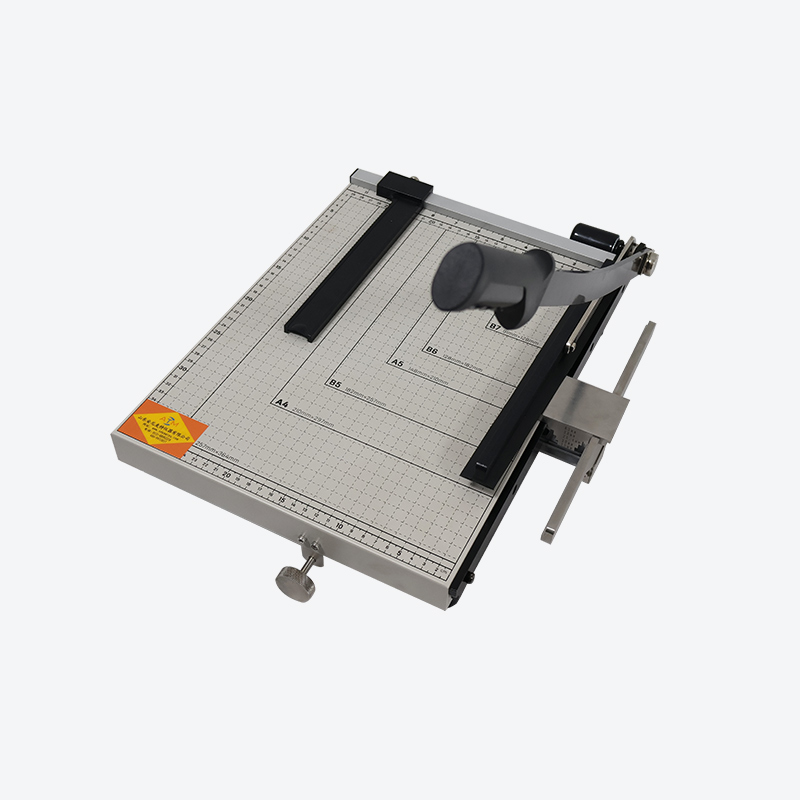
Digital instruments decide when the burst has happened by watching for a pressure drop after a peak. That detection threshold is a setting, and a setting that is too insensitive will carry the ramp past the true peak and record a higher value; one that is too sensitive will trigger on a fluctuation and record a low value. The setting should be documented, locked, and identical across instruments that are expected to produce comparable data.
Operator technique matters at the margins: whether the specimen is centred, whether the clamp is closed fully before the pump starts, whether the previously used range is appropriate, and whether the instrument has been given its warm-up period. Electronic instruments in particular need a warm-up before the sensor stabilises, and a cold instrument tested first thing in the morning is a classic source of a "Monday morning" bias.
| Symptom | Most probable cause | Quick check | Correction |
|---|---|---|---|
| All results shifted high, consistently | Pump running fast; diaphragm stiffened; clamp pressure low | Timed volume check; bulge test; clamp gauge | Service pump; replace diaphragm; reset clamp |
| All results shifted low, consistently | Air in circuit; slow pump; sensor offset | Bleed and retest; flow check; reference gauge | Bleed, top up, recalibrate |
| Scatter increased, mean unchanged | Diaphragm nicked or domed; worn clamp seals; specimen prep | Visual inspection; check cut edge quality | Replace consumables; sharpen die |
| Readings wander during a shift | Fluid level falling; leak; temperature drift | Inspect fittings for seepage; check level | Reseal; top up; allow warm-up |
| Fails at the clamp edge | Burred or damaged clamp face; under-clamping | Inspect clamp faces; check impression | Dress or replace clamps |
| Sheet crushed or flute-collapsed | Over-clamping | Post-test appearance | Reduce clamp pressure to minimum effective |
| Double pop on multi-ply | Plies failing independently | Listen and inspect plies | Discard result; check specimen condition |
The single most useful piece of discipline in burst testing is the separation of these two words. Verification asks "is this instrument reading correctly today?" Calibration asks "how far is it from true, and what adjustment corrects it?"
Verification is done with reference foils of certified bursting value. The procedure is simple but has rules that are routinely broken:
Verification should happen at least monthly, and additionally after a diaphragm change, after any maintenance that disturbs the hydraulic circuit, after the instrument is moved, when results look inconsistent, and before an audit or a critical production run. Monthly is a floor, not a target: a laboratory running several hundred bursts a week should verify weekly.
What foils must never be used for is calibration. Foil and paper deform differently — foil yields locally and abruptly, paper redistributes stress through a fibre network — so a foil result cannot define the absolute accuracy of a pressure channel. Foils check the whole instrument end to end, which is exactly what you want for verification and exactly what you must not rely on for adjustment. If the foil mean falls outside tolerance after you have eliminated clamping, diaphragm, air and rate as causes, the instrument needs recalibration against a deadweight tester or a calibrated reference gauge, performed by someone competent to do it.
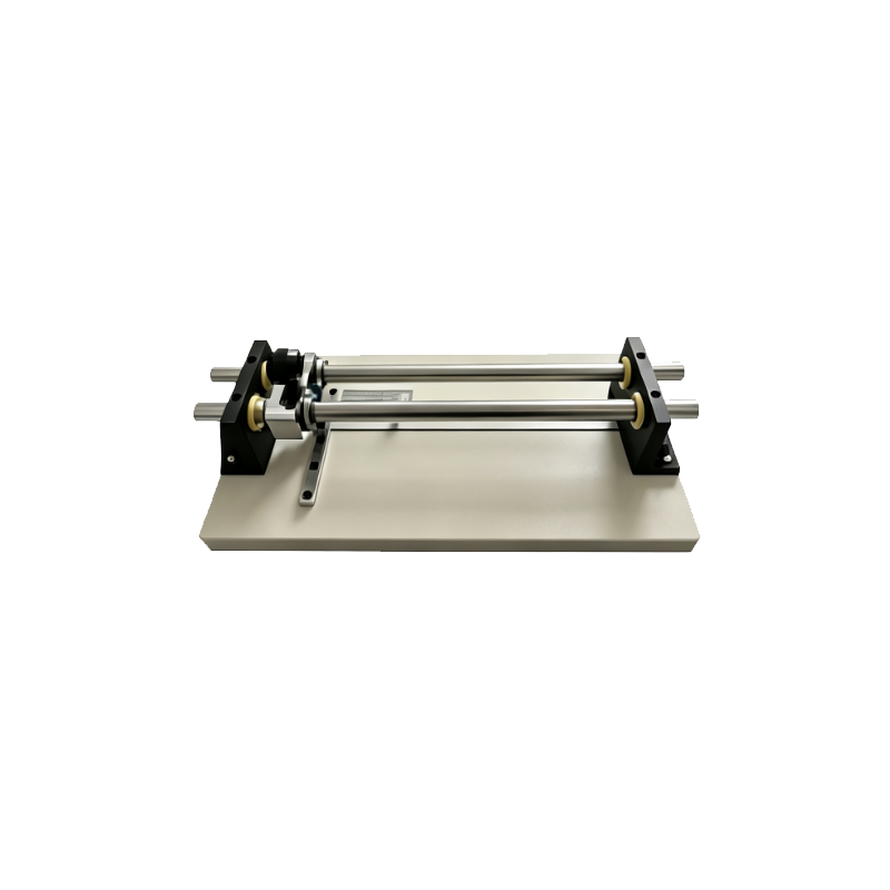
Most drift is preventable with a schedule that takes less than an hour a month. The table below is a workable baseline; adjust the intervals to your test volume, but do not drop the daily items, because they are the ones that catch developing faults while they are still cheap.
| Interval | Task | Why it matters |
|---|---|---|
| Daily, before use | Clean clamp faces; inspect diaphragm visually; check fluid level; check for seepage; verify instrument is level; allow warm-up | Debris under the clamp causes slip and false high results |
| Daily, after use | Remove paper dust from diaphragm and clamp area; wipe any fluid spill immediately | Grit embeds in rubber and creates permanent nicks |
| Weekly | Bleed the hydraulic circuit; lubricate pneumatic clamp mechanism if fitted; clean guide rods | Trapped air is the most common cause of low, unstable readings |
| Monthly | Foil verification with ten sheets; timed pump-flow check; inspect seals; check clamp pressure setting against gauge | Catches slow drift before it reaches a certificate |
| Quarterly or by count | Replace diaphragm; replace worn seals; full fluid change with fresh filtered fluid | Consumables degrade invisibly; count-based replacement is defensible |
| Annually | Recalibrate pressure channel against a reference standard; full service inspection | Provides the traceability that audits and customer approvals require |
Two habits make the schedule real rather than aspirational. First, keep a logbook that records every diaphragm change, every fluid top-up and every foil verification with its mean and range; trends in that log predict failures better than any single reading. Second, keep a control chart of foil verification means. A control chart of the reference material, not of production samples, is the only chart that separates instrument drift from process drift.
Instrument selection is usually decided on price and then regretted on throughput. The specification items that actually matter are these.
| Aspect | Hydraulic (fluid) | Pneumatic (air) |
|---|---|---|
| Pressure stability | High; fluid is effectively incompressible | Lower; air compresses, rate control is harder |
| Accuracy at high ranges | Good | Limited |
| Maintenance burden | Fluid, seals, bleeding, diaphragm | Filters, condensate traps, regulators |
| Best fit | Laboratory, certification, board and high-strength grades | Fast field or line-side checks on paper grades |
| Portability | Bench instrument | Compact and transportable |
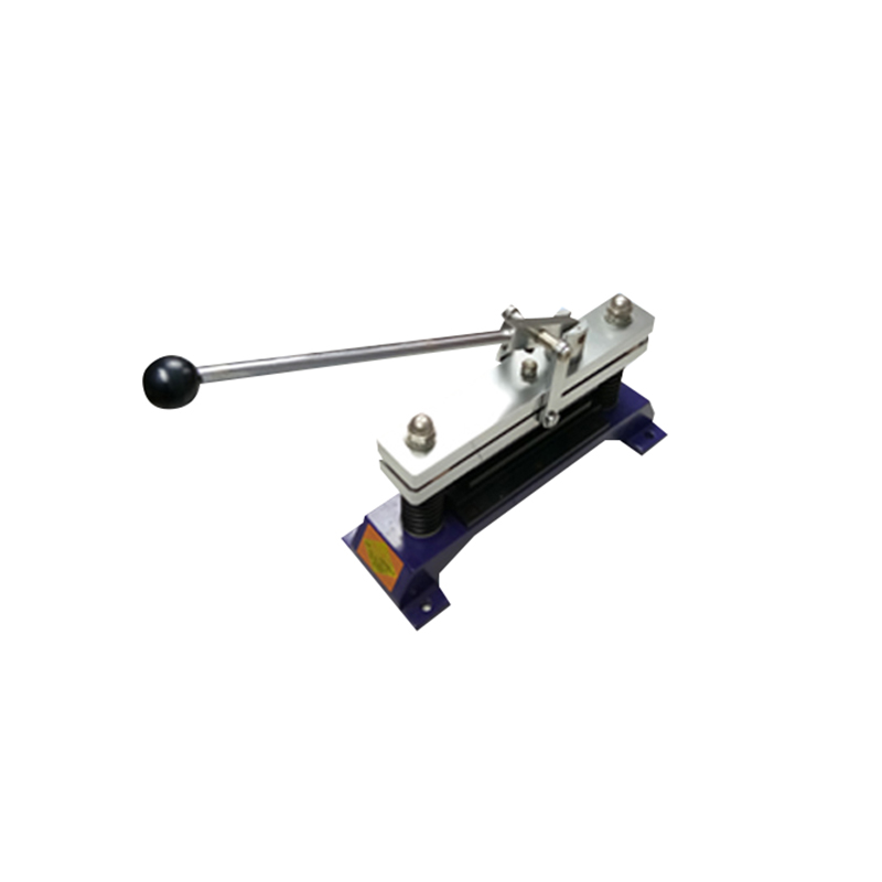
Burst strength answers a specific question: how much uniform biaxial pressure can this sheet take before it fails? Several neighbouring tests answer different questions, and substituting one for another is a common cause of specifications that do not predict field performance.
A well-designed incoming inspection plan for packaging board usually carries burst, edge crush and grammage together, and adds internal bond when delamination complaints appear. Burst on its own is a good production control number and a poor predictor of box performance.
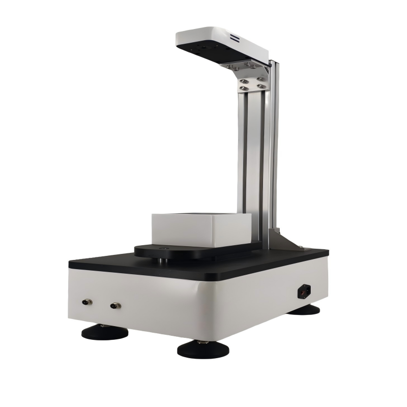
It measures the peak hydraulic pressure required to rupture a clamped sheet through a rubber diaphragm, expressed in kPa or psi. The reading includes the diaphragm's own resistance, which is why diaphragm condition is part of the measurement rather than a maintenance detail.
Because every failure mode that matters is invisible from the outside. A stiff diaphragm, a pump running 8 % fast, a clamp at half its set pressure or a bubble in the hydraulic line all produce a complete, plausible test with a wrong number. Check in this order: pump rate, diaphragm condition and position, clamping pressure, air in the circuit, then sensor calibration.
Burst index is better for comparing materials of different grammage, because it normalises out the weight effect. Bursting strength itself is better for matching a customer's specification, because that is the figure most specifications quote. Report both.
At a fixed test count or a fixed calendar interval, whichever comes first, and immediately if bulge resistance falls outside the standard's limits or the surface shows nicks, hardening or a permanent dome. Set your own count-based interval from your replacement history rather than relying on a generic figure.
No. Foils verify that the instrument as a whole is reading correctly within a working tolerance. Calibration requires a deadweight tester or calibrated reference gauge, because foil and paper deform differently and foil cannot define the accuracy of a pressure channel.
The board method asks for at least twenty valid bursts for a single reported mean, or ten per surface where both faces are reported. Given typical coefficients of variation of 4–8.5 % within a laboratory, fewer specimens produce confidence intervals too wide to support a pass or fail decision against a tight specification.
Different clamping, different diaphragm age, different conditioning history and different replicate counts all contribute, and interlaboratory variation of 6–10 % on the mean is normal. Differences below about 10 % between laboratories should not be treated as proof of a material difference without a correlation study.
Yes, substantially. Water plasticises fibre bonds, so a damp sheet bursts at a lower pressure than a conditioned one. Testing outside the standard atmosphere produces numbers that describe the room rather than the paper.
A bursting strength tester is a simple instrument wrapped around a difficult measurement. The physics is straightforward — clamp, pressurise, rupture, record — but almost every component between the sheet and the display can shift the number without announcing itself. The laboratories that get reproducible burst data are not the ones with the most expensive instruments. They are the ones that treat the diaphragm as a measured component, control clamping pressure as a set point, verify monthly with reference foils, chart those verifications, and refuse to adjust calibration until they have eliminated the four mechanical causes that precede it.
If you are specifying a tester, buy the range that matches your materials, pay for pneumatic clamping, and insist on easy diaphragm access. If you already own one, start with a timed pump-flow check and a foil verification this week; those two measurements will tell you more about your data quality than any amount of reviewing certificates from last year.

Shandong Annimet Instruments Co., Ltd., established in 2007, is a professional manufacturer integrating R&D, production, and sales of laboratory testing instruments and sample preparation equipment. With nearly two decades of industry experience, we are committed to delivering reliable quality testing solutions to clients worldwide.
Contact: +86 400-9933-057
Company Address: Factory Building 105, No. 155, Xinmao Qilu Science and Technology City, No. 299 Zidong Avenue, Tianqiao District, Jinan City, Shandong Province
E-mail: anmt_test@126.com
Fax: +86 0531-88092218
Copyright © 2026 Shandong Annimet Instruments Co., Ltd. All rights reserved
خريطة الموقعيستخدم هذا الموقع ملفات تعريف الارتباط لضمان حصولك على أفضل تجربة على موقعنا.

 English
 Español
 Pусский
 Français






 هاتف
تعليق
(0)